SPEED SENSORS
No sensor measures speed directly. They all count something that repeats, then a controller divides by time. Follow one gear tooth from the shaft to the display and the whole idea becomes clear.
PART 7 OF 25 | 4 MIN READ | BY SUBODH RAJ
Step by step
- A gear with 60 teeth is fixed on the shaft. Each tooth is a repeating feature that the sensor can detect.
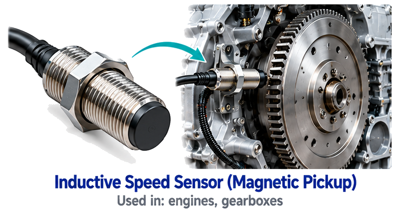
- A sensor is mounted close to the teeth, usually 0.5 to 1.5 mm away. For an inductive pickup the passing steel changes the magnetic field. For a Hall sensor it changes the field around a small magnet. For an optical sensor it breaks a beam.
- Each tooth produces one electrical pulse. The pulse is a voltage spike for a magnetic pickup, or a clean square wave for a Hall or optical sensor.
- A counter or controller measures how many pulses arrive in a fixed time, or the time between two pulses.
- It converts: RPM = pulses per second x 60 / teeth per revolution.
Suppose the controller counts 1,200 pulses in one second from the 60-tooth gear. That is 1,200 / 60 = 20 revolutions per second, or 1,200 RPM. If the shaft slows and only 300 pulses arrive, the answer becomes 300 RPM. Nothing in the sensor changed, only the pulse rate.
Which sensor suits which job
| Sensor | Strength | Limit |
|---|
| Inductive pickup | No power needed, very rugged | Weak signal at very low speed |
| Hall-effect | Works down to zero speed | Needs power |
| Optical | Fine resolution | Dirt and oil block the beam |
| Encoder | Speed plus direction and position | Costlier |
| Tachogenerator | Smooth analogue voltage | Brushes need care |
| Doppler radar | No contact with wheel or ground | Used mainly on vehicles |
Remember: Low-speed accuracy depends on counting method. At very low speed, measure the time between pulses instead of counting pulses per second, or the display will jump.
A zero-speed switch uses the same pulses in a simple way. If no pulse arrives for a set time, the shaft is considered stopped and an output trips. That is how a conveyor knows a belt has broken.
The 8 sensors in this part
Each card below shows the sensor in use, what it is and how it works, and where you will find it.
SENSOR 1 OF 8
Inductive Speed Sensor (Magnetic Pickup)
An inductive speed sensor (magnetic pickup) has a coil wound around a magnet. When a metal gear tooth passes by, the magnetic field changes and a voltage pulse is generated in the coil. The pulse frequency is proportional to the speed. It needs no power supply and is very rugged, so it is used on engines and gearboxes.
USED IN
enginesgearboxes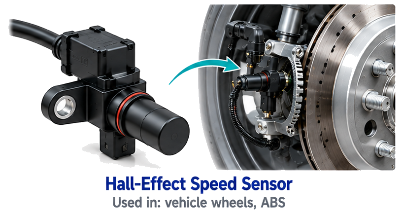
SENSOR 2 OF 8
Hall-Effect Speed Sensor
A Hall-effect speed sensor detects the teeth of a gear or a magnetic ring using a Hall chip. Each tooth that passes causes a change in the magnetic field and gives a clean square-wave pulse. It can sense even very low speeds down to zero, so it is used for wheel speed in ABS systems.
USED IN
vehicle wheelsABS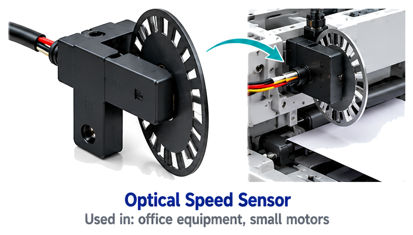
SENSOR 3 OF 8
Optical Speed Sensor
An optical speed sensor uses a light beam and a slotted disc or a reflective mark on a rotating part. Each time the beam is cut or reflected, a pulse is produced. Counting these pulses per second gives the speed. It is accurate and low cost but needs a clean environment.
USED IN
office equipmentsmall motors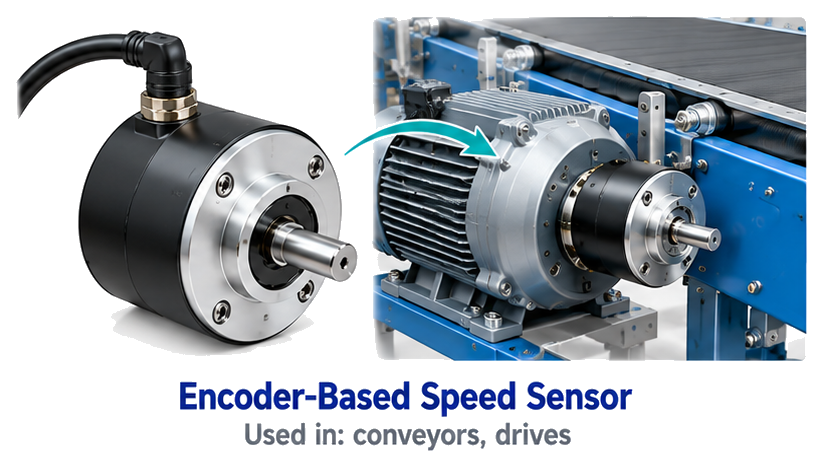
SENSOR 4 OF 8
Encoder-Based Speed Sensor
An encoder-based speed sensor uses the pulses of an encoder fitted on a shaft. The controller counts how many pulses arrive in a fixed time, or measures the time between pulses, and converts this to RPM. It gives accurate speed and also direction, so it is used in drives and conveyors.
USED IN
conveyorsdrives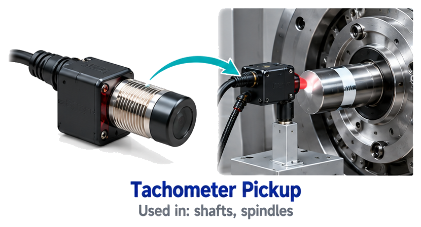
SENSOR 5 OF 8
Tachometer Pickup
A tachometer pickup senses the rotation of a shaft, usually by detecting a mark, a gear tooth or a magnet on it, and gives a signal for each turn. A meter or controller then displays or uses the RPM. It is a simple way to check and monitor shaft speed.
USED IN
shaftsspindles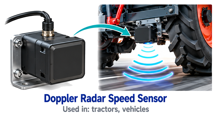
SENSOR 6 OF 8
Doppler Radar Speed Sensor
A Doppler radar speed sensor sends out radio waves toward a moving object or the ground. The reflected waves come back with a slightly different frequency, and the difference is proportional to speed. It measures speed without any contact or wheel, so it is used on tractors and vehicles.
USED IN
tractorsvehicles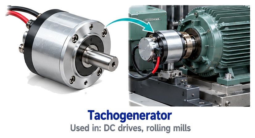
SENSOR 7 OF 8
Tachogenerator
A tachogenerator is a small DC or AC generator fitted on a motor shaft. The faster the shaft turns, the higher the voltage it produces, so the output voltage is a direct measure of speed. It is simple and gives a smooth analogue signal, so it is used in DC drives and rolling mills.
USED IN
DC drivesrolling mills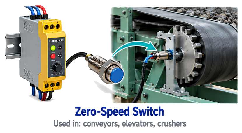
SENSOR 8 OF 8
Zero-Speed Switch
A zero-speed switch checks whether a shaft or machine is moving or stopped. It senses rotation using a proximity or magnetic sensor and gives a signal when the speed falls below a set value. It is used for safety and protection on conveyors, elevators and crushers, to detect a stall or a belt break.
USED IN
conveyorselevatorscrushersWant all 250+ sensors in one place?
The Master Sensor Handbook explains every sensor with its picture, definition and where it is used.
Buy the Master Sensor Handbook | INR 199Tap the button to message us on WhatsApp
Written by Subodh Raj,
EngineerX Academy. Part 7 of 25 in the Industrial Sensors series.
Comments
Post a Comment